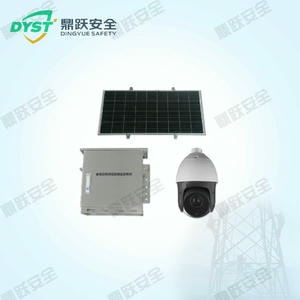
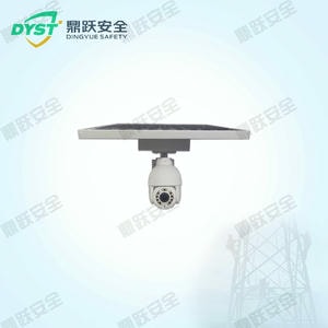
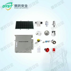


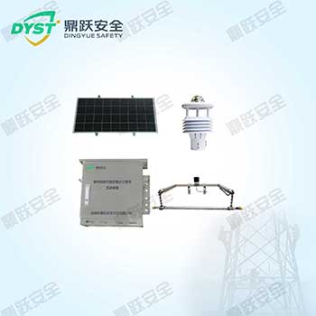


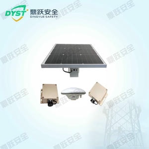


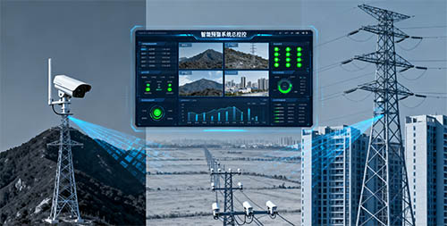
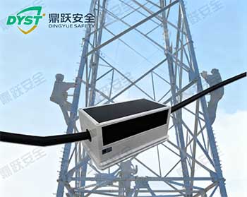
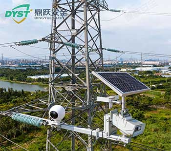
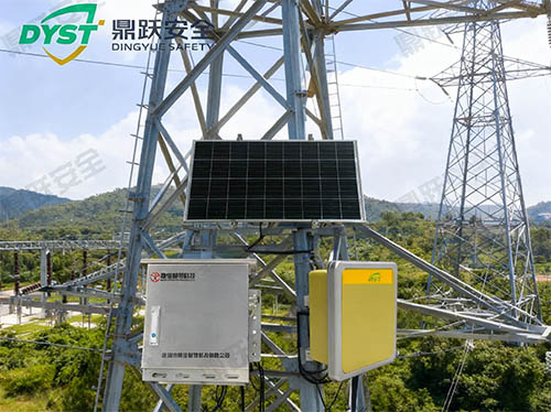
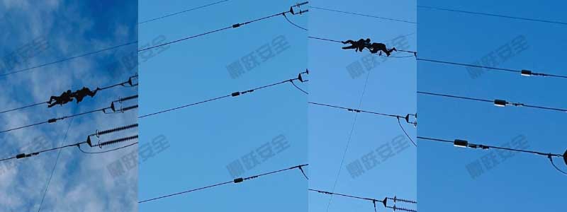
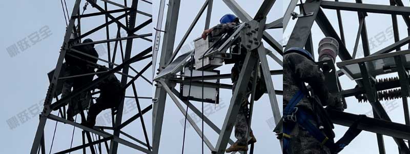
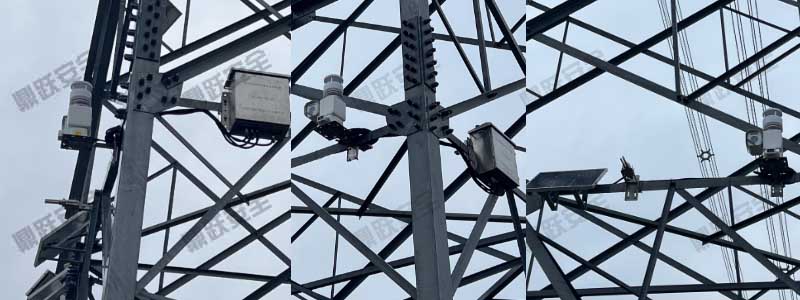
综合多场景输电线路高清视频监测与智能预警方案
电网规模扩大和输电线路多样化,线路覆盖山区、河谷、城乡结合区及高风险施工区段,存在多种潜在风险:外破行为及施工入侵山火及森林火灾风险山体滑坡、落石、泥石流等地质灾害夜间及恶劣天气下巡检困难动物靠近或异物挂线传统人工巡检效率低、盲区多、发现异···
2025-11-24
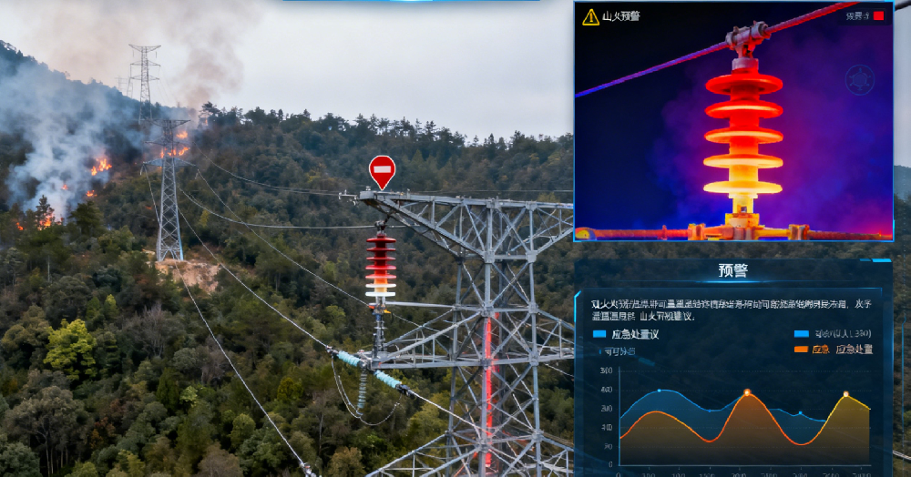
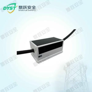
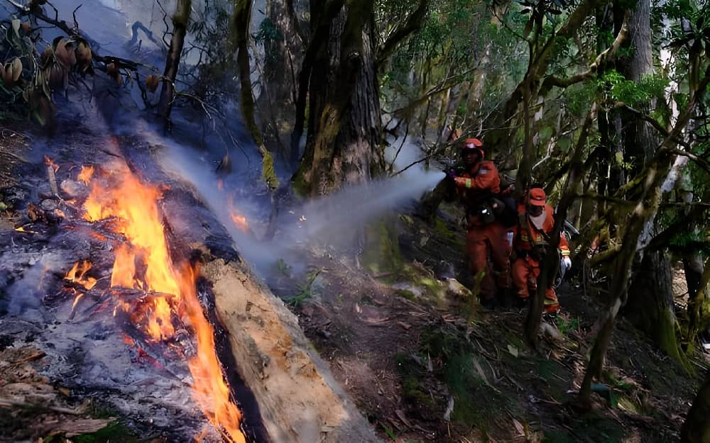
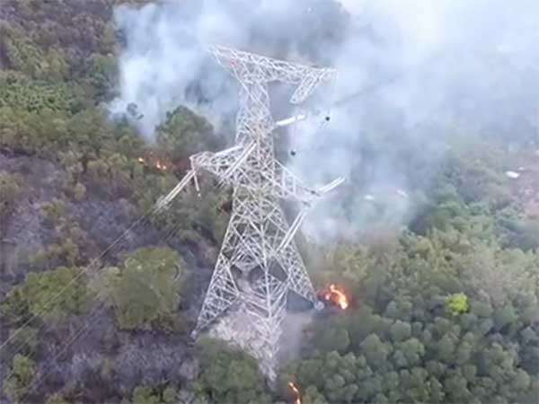
双光谱热成像输电线路山火预警视频监测方案
输电线路不断向山区、林区及野生植被茂盛区域延伸,线路运行安全面临的风险不断增加。尤其是山火频发区段,火灾可能造成线路停运、塔杆损坏、导线熔断及电网大面积瘫痪。传统巡检手段在林区、山谷及夜间场景中存在以下问题:巡检周期长,火点发现延迟夜间及烟···
2025-11-24

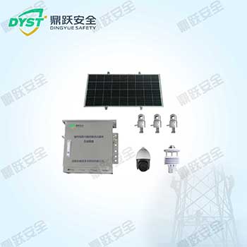
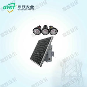
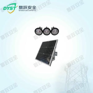
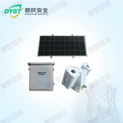
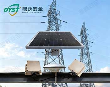
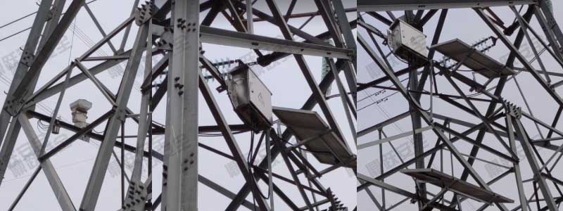
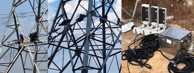
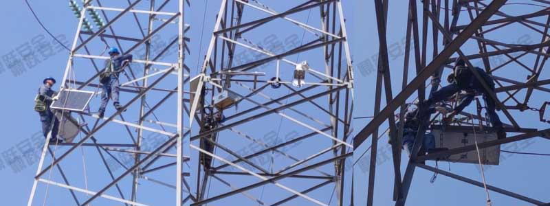
AI智能分析型输电线路视频监测系统方案
输电线路数量及电网规模的扩大,线路运行环境越来越复杂,尤其是跨山区、跨河谷和城乡结合区段。传统人工巡检方式存在:巡检效率低,周期长难以发现隐蔽风险和微小异常盲区较多,夜间及恶劣天气无法保障监测数据分散,难以统一分析为实现线路全程可视化、智能···
2025-11-24
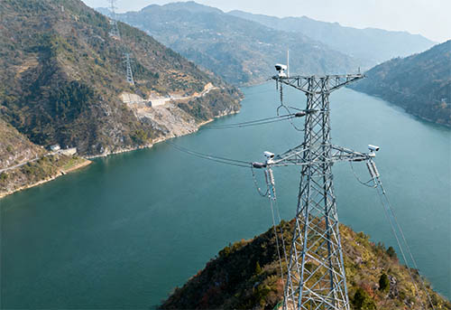
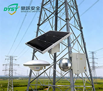
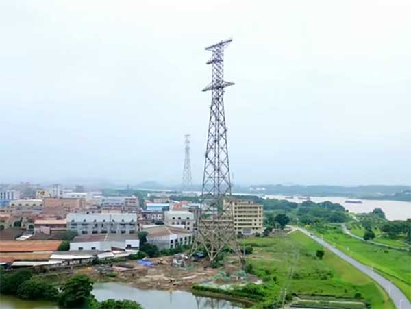
跨江跨谷输电线路高清视频监测方案
跨江、跨谷输电线路具有跨度大、环境复杂、施工及维护难度高的特点。沿线常穿越高速公路、铁路、河流、峡谷及深山地带,线路运行受外界影响风险高,如:高塔结构受风力影响明显外力破坏易发生在施工区及船舶水域道路及铁路施工可能威胁线路安全江河水位变化带···
2025-11-24

输电线路视频监测系统总体建设方案
随着电网线路跨越场景增多、外力破坏频发、极端天气影响加剧,传统人工巡线已难以满足实时性与精确性需求。视频监测系统能实现 7×24 小时可视化巡查,提升运维效率与线路安全。
2024-09-23
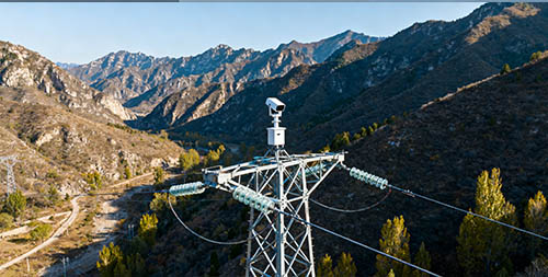
山区输电线路可视化视频监测系统建设方案
我国山地地形广泛,输电线路在山区分布密集,山高坡陡、沟谷深邃,植被茂密且地质结构复杂。山区线路运行环境恶劣,常受滑坡、泥石流、树木倒伏、雷暴大风、野火等自然因素影响,同时存在巡检难、周期长、盲点多等问题。为提升山区输电线路安全运行水平,
2024-09-06
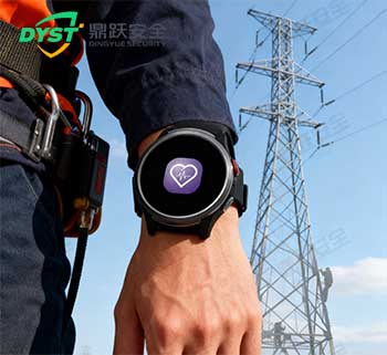
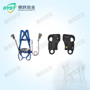
电力作业智能手环整体解决方案
电力运维现场长期处于高风险、高强度、高机动性的工作状态,人员作业分散、环境复杂、突发危险多。传统管理方式常依赖人工汇报或离线记录,人身安全保障和健康监测存在明显滞后。近年来,随着可穿戴设备技术成熟,以智能手环为载体的实时监测方案逐渐成为行业···
2025-11-26
北斗高精度智能安全帽解决方案
随着电力施工、石油化工、轨道交通、市政工程等行业安全管理要求不断提升,传统安全帽仅具备基础防护功能,难以承担实时监控、人员定位、行为预警等更高层次的安全管理需求。特别是在复杂、危险及多人员交叉作业环境中,如何实现“人员可视化管理、作业可控化···
2025-11-26
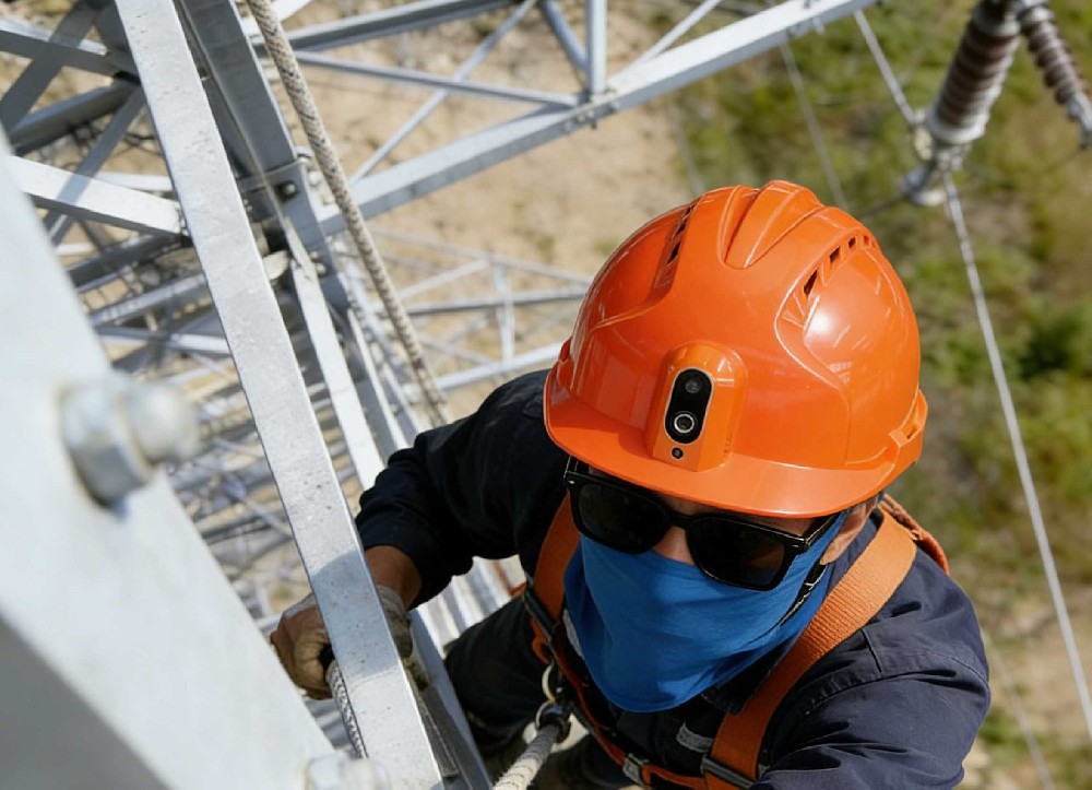
智能头盔解决方案
在电力巡检、建筑施工、矿区作业、铁路巡查等高风险行业中,一线人员长期处于复杂、多变、不可预知的环境。传统安全帽仅具备基础的物理防护功能,无法满足当下数字化、精细化、智能化的现场管理需求。而“智能头盔”作为新一代可穿戴式现场指挥终端,将 高清···
2025-11-26
执法记录仪移动视频监控解决方案
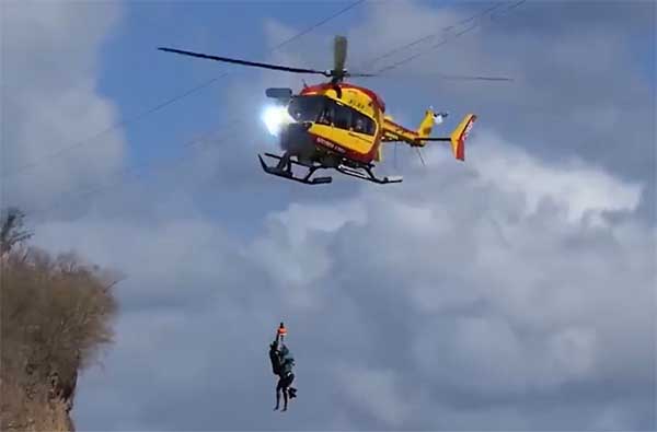
在环境监测、公共交通运营、石油开采、建筑施工、抗洪救灾、电力高压线路抢修等各类高风险、复杂户外作业场景下,传统的固定监控方式已经难以满足移动化、实时化、全覆盖的现场管理需求。作业人员需在不停移动的过程中记录现场环境、工况变化、风险点以及应急···
2025-11-26
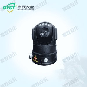
布控球智能现场安全管理解决方案
在环境监测、公共交通、石油开采、施工工地、抗洪救灾、电力高压线抢修等作业现场,往往存在环境复杂、作业风险高、指挥协同难度大等特点。传统的固定视频监控难以覆盖临时区域、移动作业点和突发性抢险场景,无法满足快速安装、灵活部署、高清取证和远程调度···
2025-11-26
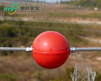
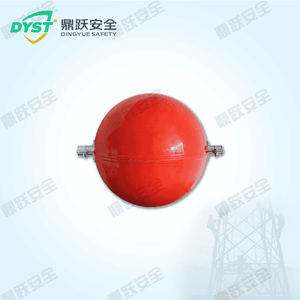
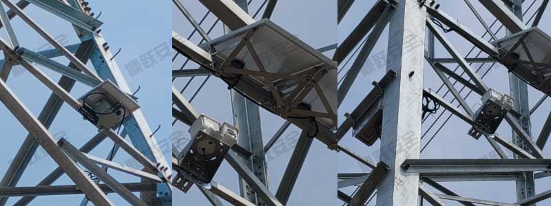
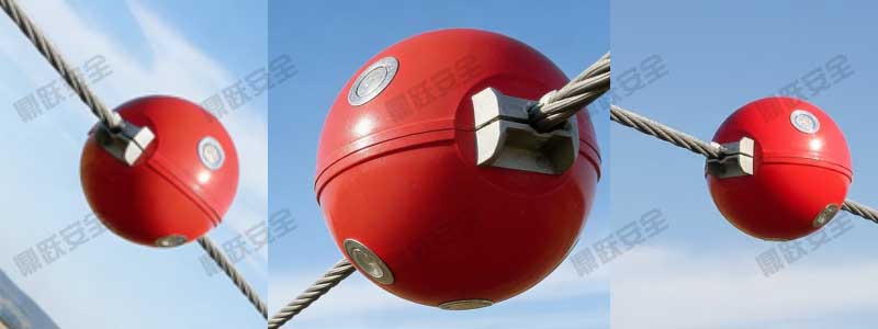
输电线路航空标志球解决方案
电网建设的迅速发展,跨江、跨河、跨高速、跨山谷、跨铁路等高压输电线路越来越多。这些线路在保障能源输送的同时,也对空中通航安全带来了潜在风险。特别是低空飞行的直升机、农林作业飞机、巡线无人机等,在能见度不佳或复杂地形下更容易与输电线路发生碰撞···
2025-11-26
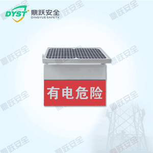
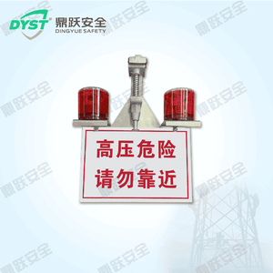
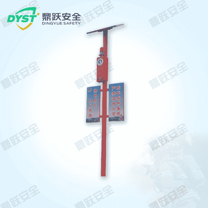
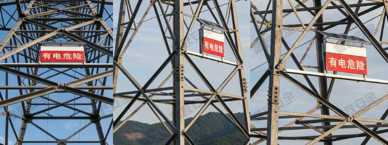
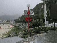
电力智能安全警示器解决方案
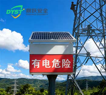
电力施工场景、配网巡检现场以及电力抢修作业的复杂化,传统静态警示牌在夜间或视线不佳环境中的提示能力有限,存在“看不清”“反应慢”“无主动预警”等问题,已无法满足当前电力安全生产的智能化需求。电力智能安全警示器作为新一代主动式现场安全防护设备···
2025-11-26

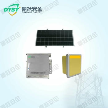
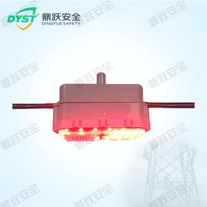
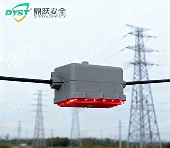
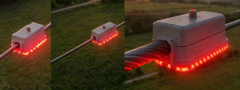
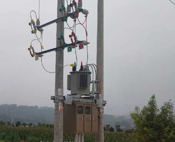
高压线防外破警示灯整体解决方案
我国电网规模不断扩大,高压架空输电线路跨越城市道路、山区农田、施工区域的数量逐年增加。由于外部施工、机械作业、运输车辆超高、无人机误闯、山火等因素持续增多,高压线路外破事件依旧高发,对电网安全运行、人身安全和社会稳定构成巨大威胁。传统的防外···
2025-11-26

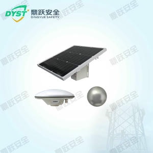
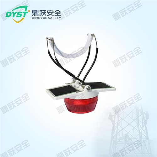
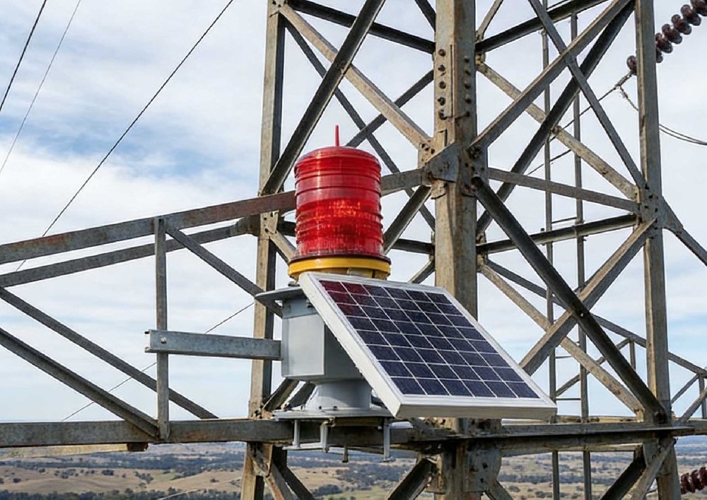
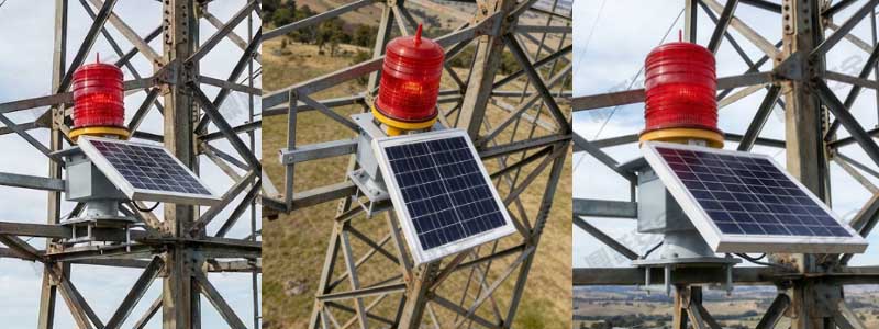
太阳能航空障碍灯解决方案
城市建设高速发展以及电力、通信、交通等基础设施的不断加固,高层建筑、铁塔设施、超高烟囱、山地风电场及桥梁等高耸结构物数量持续增加。为了确保航空飞行安全,民航法规要求所有高于障碍限高的建筑及设施须安装航空障碍灯,用以在夜间或能见度较低条件下提···
2025-11-26
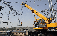
高压取电防外破警示装置解决方案
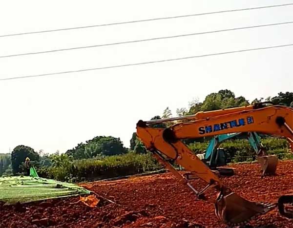
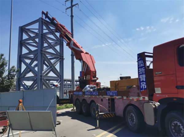
近年来,随着城乡基建工程量的不断扩大,吊车、挖机、运输车辆等大型机械频繁涉入电力通道区域,导致高压线路外破事故呈上升趋势。外力破坏已成为威胁电网安全的主要隐患之一,其中吊车臂杆误碰导线、塔吊提升作业误入电力保护区等情况屡见不鲜。传统的警示方···
2025-11-26
吊车近电预警装置在电力应急的方案
在高压输电线路、变电站及其他带电作业区域,吊车等大型施工机械在作业过程中存在误入安全防护距离的风险,可能引发电弧闪络、触电事故或设备损坏。为保障作业人员和设备安全,同时提高电力应急响应能力,采用近电预警装置对吊车进行实时监测与预警显得尤为重···
2025-05-05
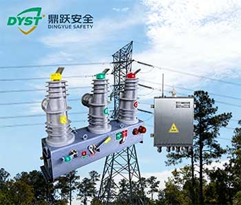
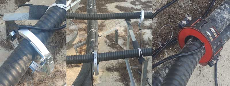
配网行波型故障预警与定位装置方案
配电网智能化水平不断提升,传统依靠录波器、保护装置、人工巡线等方式的故障定位模式,已难以满足“快速、精准、可视化”的现代电网运维要求。配网线路分布广、接线复杂、故障类型多样,尤其在分布式电源大量接入、负荷波动显著的情况下,线路发生瞬时性接地···
2025-11-25

配电故障可视精灵装置方案
配电网规模不断扩大、负荷持续增长以及分布式能源的大量接入,传统的人工巡检与事后排查方式已无法满足快速、精准、智能化运维的要求。故障定位不及时、巡检效率低、停电范围广、抢修时间长等问题日益突出。为提高配电网的运行可靠性与数字化水平,迫切需要一···
2025-11-25
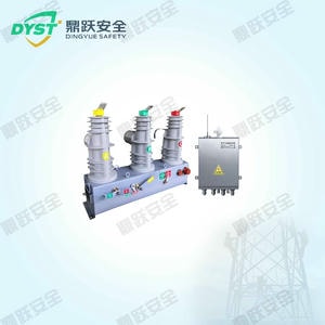
新型一二次融合成套柱上断路器故障测距装置方案
配电自动化建设的不断加速,传统柱上断路器(分界开关)在故障定位、短路隔离、遥信遥测等方面已逐渐难以满足数字化电网的要求。传统设备普遍存在以下问题:测距功能缺失或精度低,故障区段锁定效率不足。二次系统依赖外部电源及复杂接线,可靠性弱。现场巡检···
2025-11-25

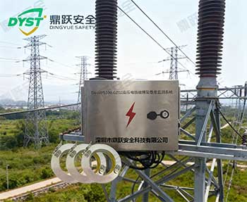
架空暂态录波型远传故障定位监测方案
电网规模不断扩大、线路跨区跨境输电比例提升,架空输电线路在复杂地形、覆冰、大风、雷害等因素影响下,故障概率显著增加。传统故障指示器依赖工人巡视排查,不仅耗时长,还容易因地形障碍或天气因素导致排查延迟。特别是在输电线路跨越山区、深谷、河流、林···
2025-11-25
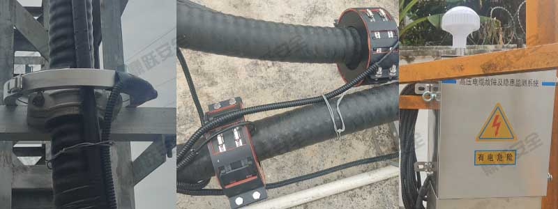
高压电缆故障及隐患监测方案
城市电网结构不断扩张,高压电缆已成为输电系统中最关键的组成部分之一。电缆一旦发生故障,往往会导致大面积停电、重大经济损失,甚至带来安全事故。传统巡检方式主要依赖人工红外测温、抽检式绝缘测试,无法对电缆故障进行实时预警,也难以及时定位问题点。···
2025-11-25
分布式故障定位监测方案
配电网规模不断扩张、线路分支增多、负荷结构复杂度上升,传统依赖人工巡检、单点测控的故障查找方式已无法满足“快速定位、精准隔离、减少停电时间”的现代电网需求。一旦线路发生短路、接地、断线等故障,停电范围大、排查路径长、恢复效率低已经成为制约供···
2025-11-25
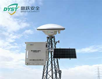
无信号区北斗智能监拍装置在线监测方案
山区、峡谷、无人区等区域基础通信条件的限制,传统依赖蜂窝网络(4G/5G)的监测设备常出现 信号弱、不稳定甚至完全无信号 的情况,导致输电线路巡检、边坡监测、地质灾害预警等场景的安全管理难度持续增加。为了实现 “无信号区域也能实时监测、远程···
2025-11-25
输电线路边坡在线监测方案
输电线路跨越山区、丘陵及复杂地质区域时,沿线常存在大量自然边坡与人工开挖边坡。这些边坡受降雨、风化、地震、植被变化及人为扰动等影响,极易发生崩塌、滑坡、落石等灾害,严重威胁铁塔稳固性和线路运行安全。随着国家对电网安全运行要求不断提高,《电力···
2025-11-25
输电线路北斗杆塔沉降在线监测方案
我国电网规模不断扩大,输电线路杆塔数量庞大且分布广泛,其基础环境复杂多变,包括软土地区、山区、河流冲刷区、冻土带、采空区等。杆塔基础沉降是最常见、也最隐蔽的结构风险之一。当沉降过快或超过设计范围时,可能造成塔身倾斜、基础开裂、导线受力不均,···
2025-11-25
输电线路北斗杆塔倾斜在线监测方案
国家电网和南方电网输电线路规模的持续扩张,杆塔数量不断增多,其分布区域呈现跨山地、跨河谷、多气候带等复杂特征。风荷载、地质变化、基坑扰动、雨水侵蚀、塔基沉降等因素均可能导致杆塔产生倾斜、旋转甚至失稳,给线路安全运行带来潜在风险。传统巡视方式···
2025-11-25
北斗雷达形变可视化在线监测方案
近年来,随着山区高速、铁路、矿山、水利工程的大规模建设,边坡稳定性、安全隐患监控显得尤为关键。传统的人工巡检方式存在滞后性、危险性高、无法持续监测等问题,已无法满足工程级安全要求。北斗雷达形变可视化监测装置依托北斗高精度定位技术与毫米波雷达···
2025-11-24
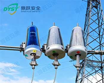
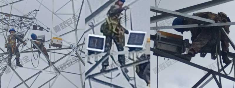
输电线路北斗风偏弧垂在线监测方案
高压、超高压输电线路不断穿越山区、河谷、风口、跨江等复杂环境,导线在大风、覆冰、高温等自然因素作用下容易产生较大幅度的 风偏、弧垂变化、振动舞动 等问题,严重时会造成相间距离不足、跳闸、线路覆冰断线、异物碰线等风险。传统的人工巡视或定期测量···
2025-11-24
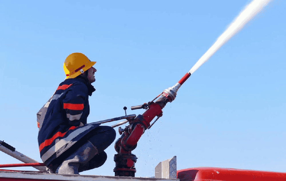
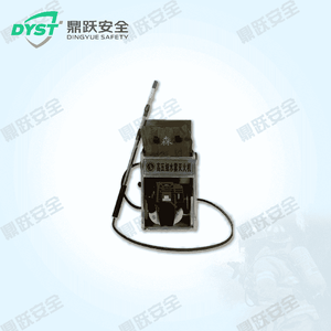
便携式移动消防炮:灾害救援与消防灭火的高效解决方案
在灾害救援和消防灭火领域,便携式移动消防炮作为一种高效、灵活的灭火设备,正逐渐成为应对火灾事故的重要工具。随着火灾事故的复杂性和多样性不断增加,传统消防设备在某些场景下难以快速响应和有效灭火。便携式移动消防炮以其轻便易携、高效灭火、操作灵活···
2025-04-14

智慧应急平台是干什么的
生活中时不时会发生突发情况,而智慧应急平台的出现将极大地提高我们在危急时刻的自救和互救能力。鼎跃安全推出一款全新的智慧应急平台,旨在为公共机构、企业和个人提供高效、智能化的应急管理工具,确保生命安全和财产保障。首先,智慧应急平台实现了全方位···
2024-05-06

智慧应急平台由什么组成
智慧应急平台能处理应急事件发生的复杂情况,实现资源的合理调配,增加事件处理响应速度。同时智慧应急平台在森林防火、台风预警、水域监测、城市执法等领域有着广泛的应用, 但是你知道它是有什么部分组成的吗?智慧应急管理平台是由数据采集和环境检测系统···
2024-05-05

智慧应急方案
随着时代的快速发展,所需处理的碎片化信息急剧增多,当应急事件发生时,这种情况对应急管理工作带来了更大的挑战。碎片化的信息意味着信息来源广泛、种类繁多、数量庞大,这增加了信息筛选、整合和分析的难度。在应急事件中,快速、准确地获取和处理信息对于···
2024-04-24

森林火灾的预防
加强森林防火宣传教育,提高公众对森林防火的认识和重视程度,也是预防森林火灾不可或缺的一环。综上所述,森林火灾预防需要综合施策,从多个方面入手,才能有效减少火灾的发生,保护森林资源和生态环境的安全。
2024-04-12

三防台风预警方案
害的发生的随机性,在较短的时间内能造成较大损失的特沿海台风是海洋重要灾害之一,具有突发性,灾点,每年都有一定数量的发生,造成沿海的重大资源损失和居民生命财产安全隐患。一旦有台风警示:预警预防、宣传、监控、监测、管理是否及时,重要原因都取决于···
2023-09-25

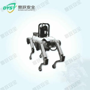
巡检四足机器人应用方案与解析
随着工业化和智能化的快速发展,电力、石油化工、隧道等特殊场景的巡检需求日益增长。这些环境往往具有高风险、高复杂性和恶劣条件(如高温、高湿、辐射、毒气等),对传统人工巡检提出了严峻挑战。巡检四足机器人作为一种智能化、稳定性高的自动巡检设备,能···
2024-12-08

无人机森林防火巡检解决方案概述
随着全球气候变化和人类活动的加剧,森林火灾已成为一种日益严峻的自然灾害。传统的森林防火巡检方法常常受到地形复杂、人力资源不足和视野受限等因素的制约,难以实现对广阔森林区域的全天候、全方位监控。无人机技术的迅速发展为森林防火提供了一种创新的解···
2024-08-26
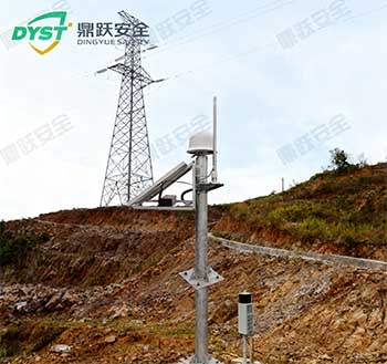
长沙市防山火在线监测装置安装项目
长沙市山区周边山林茂密、植被丰富,夏秋季节高温干燥,火险等级高。线路一旦发生山火,不仅会威胁供电安全,也可能造成大面积森林资源损失。为提升山区线路安全保障能力,运维部门在长沙市山区周边部署防山火在线监测装置,实现火情的实时自动监测和预警,为···
2025-12-02
广州市防山火在线监测装置安装项目
广州市山区地势高、山林茂密、植被丰富,夏秋季节高温干燥,火险等级高。线路一旦发生山火,不仅会威胁供电安全,也可能造成大面积森林资源损失。为提升山区线路安全保障能力,运维单位在广州市山区周围部署 防山火在线监测装置,实现火情的实时自动监测和预···
2025-12-02
南昌市输电线路分布式故障定位设备安装项目
南昌市部分区域线路跨越农田及道路,周边负荷密集且雷雨天气频发。传统故障查找依赖人工巡线,周期长且效率低,遇突发故障时可能导致停电时间延长,影响区域供电可靠性。为提高线路故障查找速度及精准性,运维部门决定在南昌市部分区域部署分布式故障定位设备···
2025-12-02
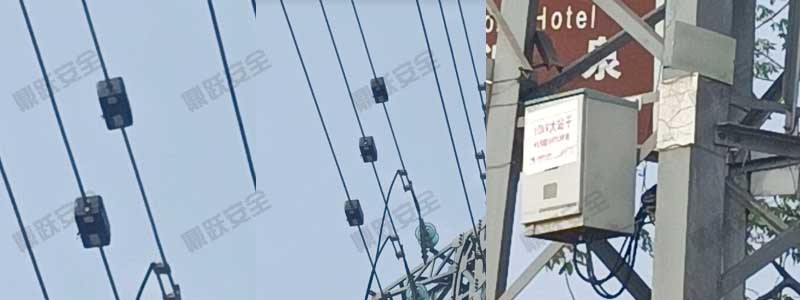
南宁市双目测距图像视频监测装置安装项目
南宁市作为重要供电通道,其中城区人流密集、活动频繁。该区域对线路安全运行的可视化监控需求尤为突出。同时,杆塔周边环境复杂,需对导线弧垂、异物距离、通道安全距离等关键参数进行精确监测。为提升线路精细化巡维与风险预警能力,运维单位在城区部分区域···
2025-12-02
昆明市山区输电线路防山火在线监测装置安装项目
昆明市山区森林密布、植被丰富,夏秋季节高温干燥,山火风险突出。山林地带一旦发生火情不仅威胁输电线路安全,也会影响区域供电和森林资源安全。为提升山区线路的安全运行能力,运维单位在昆明市山区通过部署防山火在线监测装置,构建早发现、早预警、早处置···
2025-12-02
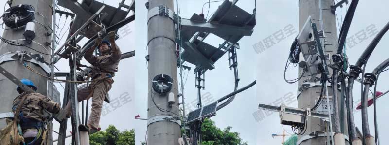
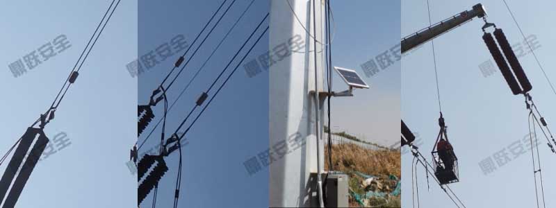
天津市输电线路在线视频监测装置安装项目
天津市输电线路跨越交通路段,为车辆密集、高速通行区段,线路安全风险较高。传统人工巡线周期长、难以及时掌握线路运行状态,尤其在恶劣天气下巡查困难。为提高线路运行可视化管理水平、及时发现杆塔及导线异常,运维部门决定在 天津市密集交通路段部署视频···
2025-12-01
电力太阳能航空障碍灯案例分享
在高压输电线路建设与运维过程中,跨越河道、山谷、交通干线的杆塔及导线极易对低空飞行器形成安全隐患。根据民航及电力行业相关规范要求,需在特定高度及跨越区段设置航空障碍灯进行警示。本文结合某500kV输电线路工程实际应用案例,系统分享电力行业太···
2026-03-02
成都航空障碍灯安装项目
高压输电线路在穿越机场、河流及低空飞行航道时,存在航空安全隐患。低空飞行器可能受到导线干扰,带来飞行安全风险。为了保障航空安全及输电线路运行安全,运维部门在03号杆塔 安装 航空障碍灯,增强导线可视性,降低低空飞行碰撞风险。
2025-12-25
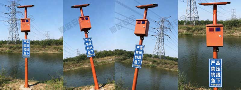
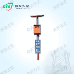
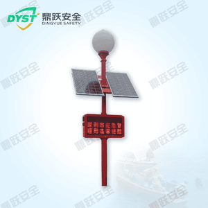
衢州高压线下防垂钓智能警示杆安装项目
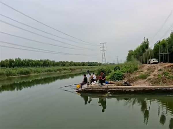
沿线水域及河道常有垂钓活动,部分高压线路杆塔附近存在垂钓触碰线路的风险,容易引发停电、设备损坏或人身安全事故。为了保障线路安全和公共安全,运维部门在11号杆塔周边水域安装高压线下防垂钓智能警示杆,实现智能提醒、实时监控和异常告警。
2025-12-25
郴州电力智能安全警示器安装项目
高压输电线路沿线存在施工、车辆通行及农用机械作业等外部风险,容易发生触碰或接近高压线路的危险情况,影响线路安全与人员安全。为了加强线路安全管理,运维部门在09号杆塔 安装 电力智能安全警示器,实现实时高压线路周边可视化提醒与智能告警,降低外···
2025-12-24
惠州市高压线防外破智能警示球安装项目
随着城市建设及农业作业范围扩大,高压线路周边活动频繁,外力破坏(如吊装作业、车辆碰撞、农用机械接触等)风险增加。外破不仅影响线路安全,还可能导致停电、设备损坏和人身安全事故。为提高线路安全防护能力,运维部门在12号杆塔附近 安装 高压线防外···
2025-12-22
深圳市高压取电防外破警示装置安装项目
高压取电点通常用于设备运维、应急供电和线路检修,但线路周边存在外力破坏风险,例如作业车辆或施工设备可能意外接触取电点,导致停电或安全事故。为保障线路运行安全与作业人员安全,运维部门在08号杆塔取电位置 安装 高压取电防外破警示装置,实现智能···
2025-12-22
银川市高压电缆故障与隐患监测装置安装项目
110kV作为银川市重点供电线路,负责城区及工业园区的稳定供电。01号杆段电缆长期运行,存在局部放电、绝缘老化及过温隐患,传统人工巡检难以及时发现潜在故障,可能影响线路安全稳定运行。为增强线路安全运行能力,运维部门在 01号杆塔安装高压电缆···
2025-12-17
贵阳市高压电缆故障与隐患监测装置安装项目
110kV作为贵阳市重要供电线路,承担城区及周边工业园区供电任务。由于这段电缆长期运行,存在绝缘老化、局部放电及过热等潜在隐患,传统人工巡检难以及时发现问题,存在供电安全风险。为保障关键区域安全供电,运维部门在贵阳110kV安装高压电缆故障···
2025-12-17
柳州市输电线路高压电缆故障与隐患监测装置安装项目
柳州市城区及学校周边,线路供电范围涵盖多个居民区,负荷密集,对线路安全性和稳定性要求极高。由于部分区段采用电缆与架空混合线路形式,电缆在长期运行中可能出现绝缘老化、局部放电、温升异常等隐患,传统人工巡检难以及时发现问题。
2025-12-03
清远市配网故障定位设备安装项目
清远市输电线路覆盖城区及商业区,供电负荷大,居民及商业用电对供电可靠性要求高。传统人工巡检及故障排查耗时较长,一旦线路发生故障,会造成停电范围广、恢复时间长,影响区域供电稳定。为提升配网线路运行安全性和故障处理效率,运维部门在市区部分输电线···
2025-12-03
南京市非接触式故障定位设备安装项目
南京市山区线路跨越丘陵及林地,雷雨及风荷载频繁,线路易受外力及自然因素影响发生短时故障。传统接触式故障定位方式存在停电、施工风险高及响应时间慢等问题,难以满足山区线路高效运维需求。为提升线路运行安全性和故障处理效率,运维部门在南京市山区线路···
2025-12-03
太原市分布式故障定位设备安装项目
太原市线路跨越城区与郊区结合地带,雷雨及风荷载频繁,线路容易因外力影响或天气因素发生短时故障。传统人工巡检响应慢,故障定位周期长,存在停电时间延长的风险。为提升线路运行安全性和故障处理效率,运维部门在太原市线路安装分布式故障定位设备,通过多···
2025-12-03
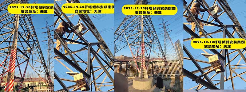
12.30天津杆塔倾斜在线监测装置安装项目
天津地区部分输电线路穿越城市道路、软土地基及施工活动密集区域,受地基沉降、地下工程施工、长期荷载变化等因素影响,个别杆塔存在倾斜风险。为加强杆塔结构安全管控,提升输电线路运行可靠性,运维单位在056号杆塔部署杆塔倾斜在线监测装置,实现对杆塔···
2025-12-30
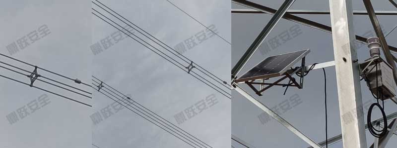
秦皇岛市防导线舞动在线监测装置安装项目
是秦皇岛地区的核心主网输电线路之一,线路跨越区域广,沿线地势开阔,当地风口明显、风速变化频繁,是导线舞动的典型高风险点。在冬季大风、强冷空气与风切变条件叠加时,导线极易出现周期性振动,造成:
2025-12-04
长春市输电线路防导线舞动在线监测装置安装项目
长春地区的重要输电通道,承担着城市中心及周边乡镇的主网供电任务。地形开阔,冬季盛行偏北风,低温与风速耦合作用明显,是导线舞动的高发区域。
2025-12-04
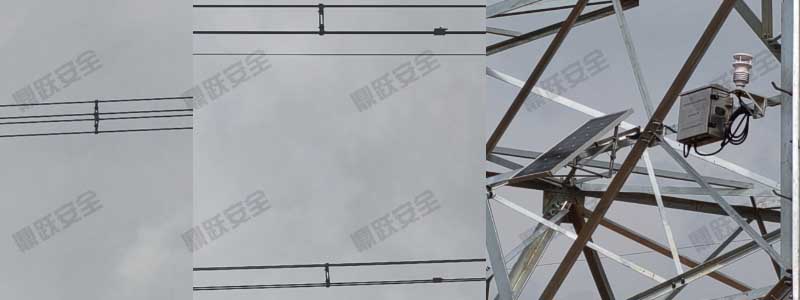
保定市输电线路微气象在线监测装置安装项目
项目名称:输电线路微气象在线监测系统建设安装地点: 保定市安装设备: 微气象在线监测装置(风速、风向、温度、湿度、气压实时采集 + 数据远程传输)完工时间: 2025年7月3日一、项目背景保定市区域属于多风、雨量适中地带。微气象变化直接影响···
2025-12-03
承德市输电线路覆冰在线监测装置安装项目
承德地区冬季气候寒冷、湿度高,线路覆冰现象频发,尤其在地形复杂、海拔起伏大,风雪天气容易导致导线覆冰加重,进而产生断线、跳闸等安全隐患。为保障迎峰度冬期间线路安全稳定运行,运维单位决定在承德较寒冷地区安装覆冰在线监测装置,实现导线覆冰厚度、···
2025-12-03
沈阳市观冰与防舞动在线监测装置联合建设项目
沈阳市国道交通干道,冬季沿海湿冷气候易形成导线覆冰,同时线路受风偏影响较大,存在舞动风险。覆冰和舞动均可能造成导线疲劳损伤、金具受力异常甚至跳闸事故,对线路安全运行带来挑战。为提升线路冰灾及风振预警能力,运维单位在国道部分区域部署观冰在线监···
2025-12-02
便携式灭火水泵的应用案例解析和分析
便携式灭火水泵在提高灭火救援效率、降低人员伤亡风险和优化现场作业流程方面具有显著意义。未来,随着相关技术的不断改进和新材料的应用,便携式灭火设备将在消防救援体系中发挥更加关键的作用,成为保障公共安全的重要装备。
2025-04-12
太阳能台风预警宣传信号杆:设计小调整,实用性更强
太阳能台风预警宣传信号杆的设计优化与全面部署,能够为深圳大鹏新区的海岸线提供更加坚实可靠的防护。
2024-10-01

智慧应急管理平台案例
嘉兴市结合全市“智慧消防”总体规划和世界互联网大会消防安保需求,围绕“一个中心”、“两大核心”、“一个支撑”,整合各方数据,综合多方资源,采用物联网+互联网技术全方位应用,开放共享信息资源平台,在桐乡乌镇运行“智慧消防”安保指挥平台,为全市···
2024-04-23

太阳能森林防火语音提示器案例
在森林防火期,只要有人员或车辆走到感应探头前方的10米范围内,系统便会自动播放森林防火指挥部提醒林区群众注意森林防火警示语音、森林火灾报警电话、宣传标语,以及《森林法》《森林防火条例》《自然保护区条例》等林业法律法规,并且语音宣传内容可以根···
2023-05-15
电力设施频发短路断线,被动防护失效,智能语音警示器来破局
走在大街小巷,不知道你有没有注意过那些耸立在路边、农田或建筑工地旁的高压配电台区和电线杆?说实话,现代城市和乡村的发展太快了,密集的电力设施早就和我们的生活融为一体。但这种“贴身”的距离,有时却成了一颗隐藏的定时炸弹。
2026-06-18
传统巡线难防突发山火,双光谱监测提前拦截火情苗头
“远水救不了近火”,这句古老的话放在现代电网的“防山火”工作里,显得格外残酷。传统的输电线路防山火,大多依赖“望远镜+双腿”的肉眼巡视,或者周期性的无人机飞手巡检。然而,面对突发性极强、蔓延速度以分钟计算的林火,
2026-06-17
冬天登塔布线太遭罪?太阳能航空障碍灯告别高空拉线
如果你去问一个电网的运维小哥,冬天最不想干的活是什么?在几十米高的铁塔上拉线接电绝对名列前茅。寒风呼呼地刮,手冻得跟胡萝卜一样,还要悬在半空中去引一根警示灯的电源线,那感觉,真的是在用生命在跟合规标准开玩笑。但不装又绝对不行。
2026-06-16
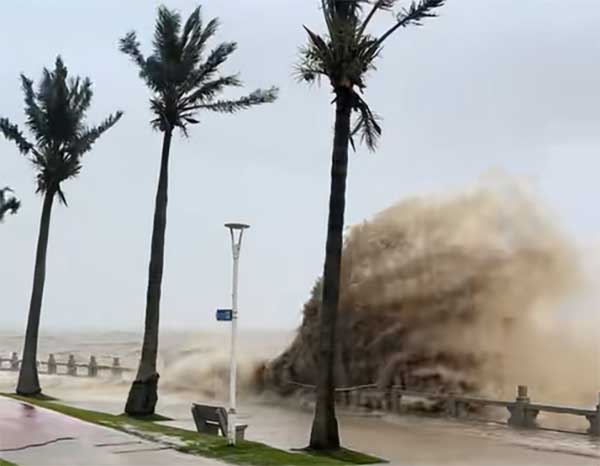
台风信号杆视听双重警示加持,高效完成海岸疏散通知
大风呼啸、海浪翻滚,当裹挟着暴雨的台风向沿海肆虐而来,那种天昏地暗的压迫感,相信每一个经历过的人都记忆犹新。面对自然灾害的突发性与随机性,沿海防汛的每一分每一秒都在与危险赛跑。现场信息断档、预警宣传滞后,往往是酿成重大财产损失与安全隐患的导···
2026-06-15
低空通航致命隐患:看不见的导线,靠标志球可视化预警
只要聊起“低空飞行”,无论是执飞救援的机组人员,还是守护电网的运维人员,心里总有一块石头放不下。飞机在1-2公里的距离内,如果肉眼识别不出前方高压线的位置,等待他们的可能就是一场严重的碰撞风险。这种双向的焦虑和担忧,
2026-06-12
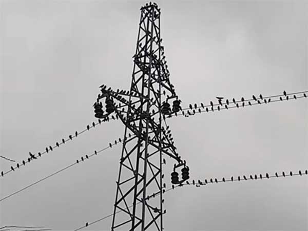
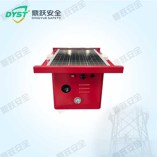
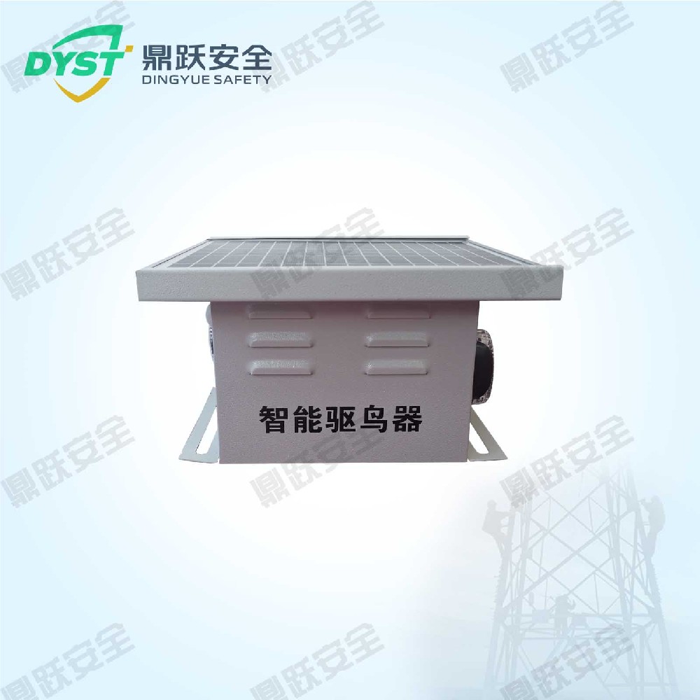
120dB大功率太阳能驱鸟器,15米全覆盖守护输电铁塔
如果让鸟儿来选房,输电铁塔绝对是它们眼中的“顶流豪宅”。站得高、视野好、没天敌,还能俯瞰整片领地。这样自带360度全景的“黄金地段”,自然吸引了无数鸟类前来打卡。起初,它们只是把这里当成歇脚的临时“驿站”;久而久之,便纷纷衔来树枝安营扎寨,···
2026-06-11
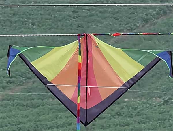
静态警示标识看不见?挂在导线上的声光警报,专治施工走神
说实话,以前防外破,大家能想到的办法无非是去工地发传单、在铁塔下刷红白漆。可结果呢?只要大型机械一进场,那些静态的警示标志在漫天尘土里约等于不存在。高空作业车辆稍有误判,碰到了架空线,造成的火灾和停电事故,哪一次不是让人脱层皮?
2026-06-18
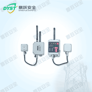
临时工地快速部署!无线免布线施工高压线危险预警系统
我们常说“高压危险,请勿靠近”,但当几十米长的吊车钢臂在工地上挥舞时,这句话往往成了一句无力的空话。城市基础建设跑出快车道,高架、公路纵横交错,可头顶的输电线也同样密集。大型机械在下面作业,就像是在雷区里盲行。
2026-06-17
远程调度实时取证,智能警示杆实现电网垂钓隐患全流程管控
对于电网运维来说,最怕的不是设备自然老化,而是那些防不胜防的“移动隐患”。尤其是到了鱼肥水美的季节,河道、水塘边那些横跨上空的高压线,就成了随时可能引爆的“地雷”。一个普通的碳素鱼竿,沾了水就是完美的导体。
2026-06-16
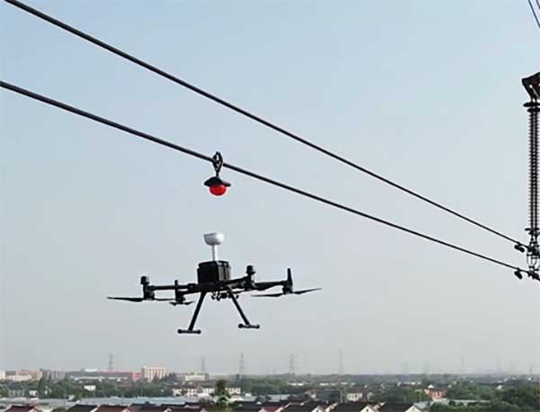
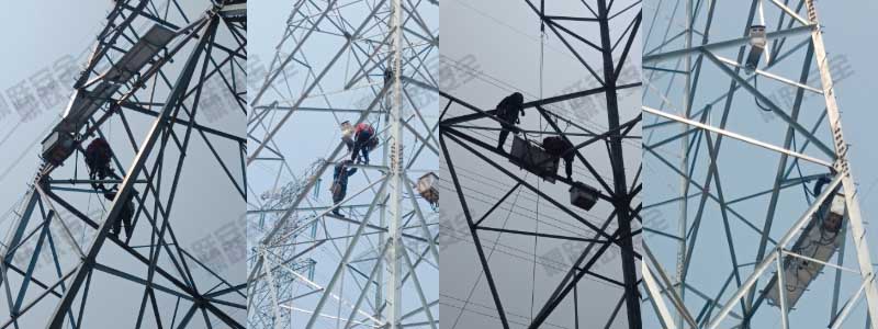
高空线路防外破不用停电登塔!无人机带电安装防撞警示装置
在过去,在高空输电线路上安装外破防护装置,意味着漫长的停电协调、艰难的人工登塔,以及无法忽视的安全风险。现如今,无人机带电挂装技术让“空中作业”成为常态。伴随低沉的蜂鸣声,一架大疆精灵4RTK无人机在山谷间稳稳升空。
2026-06-15
线路故障盲目徒步排查?可视精灵一键精准定位
有时候是一根被狂风卷起、不偏不倚挂在导线上的塑料薄膜;有时是一截脱落的广告布,在雨夜悄悄搭上线路;还有时,是风吹日晒后逐渐老化的绝缘部件,在深夜突然“撑不住了”。这些看似不起眼的隐患,如同埋在线路上的“定时炸弹”。
2026-06-12
传统警示存在致命视觉漏洞,太阳能频闪警示灯守护架空线路
很多人以为,防止高压线被外力破坏,只要挂个“高压危险”的铁牌子或者装个一直亮着的灯就够了。但事实上,在真实的施工现场或道路通行环境中,人往往处于高度专注或疲劳状态,对“静止不动”的标识和“持续常亮”的灯光极易产生视觉适应,久而久之就会形成“···
2026-06-11
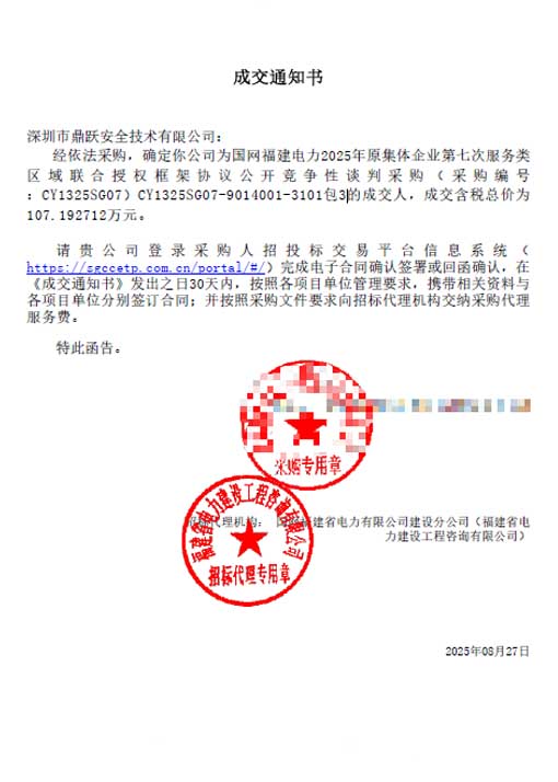
2025年8月27日 我司成功中标国网福建电力2025年联合授权框架协议采购项目!
我们怀着激动的心情宣布:在国网福建电力2025年联合授权框架协议的公开竞争性谈判采购中,深圳市鼎跃安全技术有限公司凭借综合实力、优质服务和卓越的履约能力,成功获得该框架协议的授权!
2025-12-10
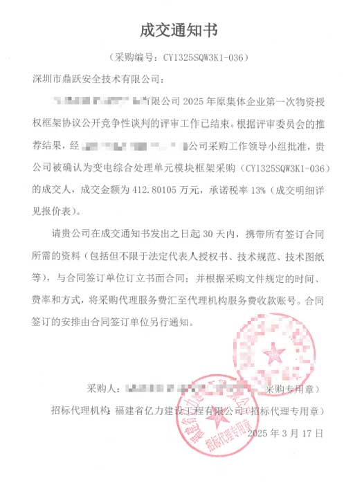
2025年3月17日 我司成功中标变电综合处理单元模块框架采购项目!
我们怀着无比激动的心情宣布:在严格的技术评审和商务谈判中,深圳市鼎跃安全技术有限公司凭借在电力自动化和硬件集成领域的深厚积累,成功中标变电综合处理单元模块框架采购项目!
2025-12-10
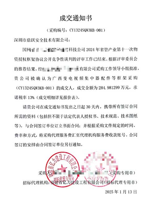
2025年1月13日 我司成功中标广西变电视频集中器配件项目!
我们怀着无比激动的心情宣布:在激烈的市场竞争中,深圳市鼎跃安全技术有限公司凭借卓越的技术实力、可靠的产品质量和完善的服务体系,成功中标广西变电视频集中器配件采购项目!
2025-12-10


I. Requirements Analysis
The current distribution network suffers from mismatched primary and secondary equipment interfaces, resulting in poor compatibility, scalability, and interchangeability; There is a lack of a coordinated testing mechanism for primary and secondary equipment. To address the challenges of expanding distribution automation coverage for incremental equipment and resolving primary-secondary mismatches during large-scale distribution network upgrades, while achieving the goal of simultaneous "four-tier" line loss management (by zone, voltage level, component, and transformer district), and to advance the implementation of simultaneous line loss management for 10(20/6) kV feeder circuits, continuously improving the precision of line loss management and enhancing operational efficiency, our company introduces a new integrated primary-secondary pole-mounted circuit breaker fault location device that perfectly resolves these challenges.
By enhancing the standardization and integration of primary and secondary distribution equipment, we improve the operational performance, maintenance quality, and efficiency of distribution equipment. This meets the technical requirements for line loss management and supports the action plan for distribution network construction and transformation. With the technical goal of achieving "safety, reliability, integration, and efficiency," and guided by demand with testing as assurance, the initiative primarily targets incremental equipment in distribution network construction and renovation. Following the principles of standardized overall design, independent functional modules, and flexible equipment interchangeability, it prioritizes addressing urgent issues in distribution automation construction—such as compatibility and scalability of primary-secondary interfaces, adding new energy measurement functions to terminals, and remote signaling jitter. This phased approach advances the integration of primary and secondary distribution equipment.
Complete set of functional requirements
1. Fault-location-capable primary-secondary integrated circuit breakers can be used for line sectioning, interconnection, branching, boundary demarcation, and similar applications.
2. The primary-secondary integrated standardized column-mounted circuit breaker comprises the switch body, feeder terminal, power supply voltage transformer, voltage transformer, current transformer, and connecting cables. The feeder terminal integrateswave value acquisition functionality, with the voltage transformer/sensor and current transformer/sensor meeting traveling wave sampling requirements;
3. Military-grade aviation connectors are used between the switch body, feeder terminals, and power voltage transformers, connected via outdoor-rated fully insulated cables. Exposed aviation connectors must seal metal conductors with waterproofing materials to enhance condensation resistance. Cable entry points for power voltage transformers require rainwater ingress protection and U-shaped clamps during installation. The cable controller side must feature a lower U-shaped clamp to prevent rainwater from flowing into the connector along the cable.
4. Capable of collecting three-phase currents, zero-sequence currents, three-phase phase voltages, or one line voltage and one zero-sequence voltage on each side of a switch, to fulfill the functions of calculating active power, reactive power, power factor, frequency, and energy collection.
5. Flexibly configure operating parameters and control logic based on actual operating conditions to handle single-phase-to-ground and phase-to-phase short-circuit faults. Direct tripping can isolate faults, with the inherent action time for phase-to-phase faults not exceeding 100 ms. Features three automatic reclosing attempts, with adjustable reclosing frequency and time intervals.
6. Provides detection and protection capabilities for phase-to-phase short-circuit faults and single-phase ground faults in low-resistance grounding systems. Supports three-stage protection for phase-to-phase short circuits, with configurable settings for all three stages' values and time delays. Supports two-stage zero-sequence protection, with configurable settings for both stages' values and time delays.
7. Capable of local identification and isolation of single-phase ground faults in low-current grounding systems, with ground fault alarm and local disconnection functions.
8. Supports both centralized feeder automation and local feeder automation functions, with the ability to switch automation modes via preset value configuration.
9. Supports the three-remote configuration requirements for distribution automation. Terminals are equipped with local/remote switchover functionality. When information security conditions are met, remote control capabilities can be enabled without altering the hardware equipment.
| Serial Number | Project Name | Technical Specifications |
| 1 | Vacuum circuit breaker | Pillar-type, rated short-circuit breaking current, number of breaking operations ≥30 times |
| 2 | Operating mechanism | Electric operation with manual override capability; instantaneous power during closing and opening ≤480W |
| 3 | Transformer Combination Mode | Includes electromagnetic current transformers, electromagnetic voltage transformers, and zero-sequence voltage sensors. |
| 4 | Feeder Terminal Unit (FTU) | (1) Telemetry; Telemetry; Remote Control: Acquire one line voltage; collect three-phase currents, zero-sequence current, and zero-sequence voltage; |
| At least 3, including switch closing position and de-energized status remote signals; 2 channels (closing, tripping) | ||
| (2) Voltage measurement accuracy: Phase voltage: ≤0.5% (Class 0.5), Zero-sequence voltage: 3P | ||
| (3) Current measurement accuracy: Phase measurement value 0.5 class (≤1.2In), zero-sequence current ≤3% | ||
| (4) Supports 4G/3G/2G five-mode adaptive operation | ||
| 5 | Fault Location | Traveling wave current sensor frequency response range; Traveling wave current sampling rate: 1 kHz to 1 MHz; ≥1 MHz |
| Number of monitoring channels for traveling wave current: 3 channels for faults | ||
| Current Sensor Frequency Response Range: 20Hz to 1kHz Fault Current Measurement Range | ||
| Fault Current Amplitude Measurement Error: 0.5 to 6000 A; ±5% and ±0.5 A | ||
| Number of fault current monitoring channels: 3 channels GPS | ||
| Beidou-2 Integrated Positioning System Synchronized Clock Accuracy: ≤0.1 microseconds | ||
| 6 | Primary and Secondary Integration Package | Fault Trip: Capable of automatically isolating phase-to-phase short circuits and ground faults on the customer side. Proactively transmits fault information upon occurrence of a customer-side fault. |
| Fault clearing time: The inherent operation time for the entire unit shall not exceed 100 ms, with the FTU operation time not exceeding 40 ms. | ||
| Feeder Automation: Supports centralized and local feeder automation, with the capability to engage and disengage. | ||
| 7 | Switch Enclosure Protection Rating | Not less than IP65 |
| 8 | Primary and Secondary Equipment Connection Design | Control Connection Method: The switch body is equipped with a 26-pin aviation connector assembly, including a connection cable. |


